Application of LOGO! in vacuum vacuum suction system
LOGO! Application in vacuum vacuum suction system Wenzhou Medical College First Affiliated Hospital Huang Yunlong Hospital vacuum vacuum suction system vacuum pump as vacuum equipment, vacuum tank vacuum storage equipment, using vacuum technology to remove the patient's body, Blood, pus, and other contaminants need to be guaranteed 24 hours a day and 24 hours a day. Using LOGO! For the application of automatic operation and conversion between two vacuum pumps, share some learning and application experience. The old-fashioned appliance control cabinets are relayed with electrical controls and a total of more than ten relays of various kinds. Due to the poor contact of relay contacts, faults often occur. PLC can use software to replace a large number of time relays and intermediate relays. This example uses simple logic control of the switching signal at each input point. Comparison of various small PLC, the input and output hardware wiring lines must go through the public input, output, and LOGO! As long as the input points are taken from the same phase power supply, and the output is a relay contact, there is no common terminal, which is quite free in hardware design. In software programming, the fault status can be compiled into text on the display panel and an alarm output is given. The cursor keys on the panel can be programmed as input switches, saving hardware investment. Based on the above comparison, this example uses LOGO! 230RC as a controller. Application Description Due to the fact that the water pumping temperature of the water circulatory vacuum pump will affect the pumping performance of the pump, two vacuum pumps are used to operate alternately. Considering that in the event of a leak in the pipeline, when a pump cannot exhaust enough to pump the vacuum inside the tank to the upper limit, the two pumps need to be operated together, ie, the operation of the “suppressionâ€. Due to the special nature of the hospital, in this example, two sets of vacuum negative piezo contact pressure gauges are used. When one group fails, the other group can be used for control. In the event of a pump failure, it can be automatically transferred to another pump. Using LOGO! The above control problem can be solved well and the alarm signal and the cause of the fault can be given, greatly improving the stability of the system and reducing the time for troubleshooting. Process Description Vacuum Vacuum Suction System The vacuum tank is used as a vacuum storage device. Two bad water vacuum pumps are used to pump air. Pipes are used to connect beds of bed equipment in hospital beds, operating room equipment belts, and pipeline terminals in medical departments. Connector. Two vacuum negative piezoelectric contact pressure gauges are installed on the pipeline for automatic control. One set is set to normal value. When the negative pressure reaches -0.06MPa, the pressure gauge contact will automatically stop the pump. When the vacuum negative pressure rises to -0.03MPa, it will automatically start the vacuum pump; the other set of pressure gauge upper and lower limit is set. For -0.066MPa and -0.026MPa as spare. A solenoid valve is installed on the intake pipe of the pump, and the solenoid valve is synchronously started and closed with the pump motor to prevent the water and air from flowing back into the vacuum system when the pump is stopped. During normal operation, the two pumps “operate†to operate, that is, one pump works first after the power is turned on. After the negative pressure reaches −0.06 MPa, the pump stops automatically. When the negative pressure of the vacuum system rises to −0.03 MPa, the pump automatically starts. A vacuum pump runs so that the system is kept within the set vacuum range. When there is a leak or special situation in the pipeline, the operation is performed in the “continuous†state, that is, after one pump starts to run for 10 seconds, another pump follows the start operation (in order to reduce the instantaneous voltage drop of the two pumps to the grid). System hardware configuration system application LOGO! See the hardware design control schematic. P1 and P2 are vacuum negative pressure contact pressure gauges. The 4 electrical contacts (contact switches) are connected to LOGO! The negative pressure value of I1~I4, P1 is set to -0.03~-0.06MPa, and the negative pressure value of P2 is set to -0.0260.066MPa.F is the solenoid valve, and the pump motor and the automation system are started and closed. SA1 is an emergency stop switch for operators to use in case of emergency. SA2, SA3 is a multi-functional switch. When it goes to manual file, it is used for emergency or maintenance; when it is transferred to automatic file, input signal to I7 and I8 to LOGO! Automatic control. If the vacuum pump stops pumping, SA2 or SA3 shifts to the stop position, leaving the inspection pump out of automatic control. I5, I6 input points through the corresponding contactor normally open auxiliary contact opening and closing signal acquisition, combined with Q1, Q2 output status, the start and stop status of the vacuum pump monitoring. If Q1 sets the output, then KM1 coil is electrically pulled in, 1 pump runs, KM1 normally open auxiliary contact is closed, I5 input signal voltage, if the motor or line has serious overload, short circuit, under voltage, lack of phase, contactor coil Short circuit and other faults, then QF2, FR1 or FU2 SA (emergency stop) hand stop automatically SA3 19 hands stop from the vacuum pump control principle, diagram electric control cabinet table LOGO! I/O assignment table address comment address comment address comment I10.03 MPa start contact 151 pump operation signal acquisition Q11 pump operation I20.06 MPa stop pump contact 162 pump operation signal acquisition Q22 pump operation I30.026 MPa start contact 171 Automatic pump Q3, help state instructions I40.066 MPa stop pump contact 182 pump automatic Q4 alarm output stop bit stop bit automatic protection, cut off KM1 coil control loop, normally open auxiliary contact reset due to coil loss, 15 lost Input signal voltage, Q4 alarm output, LOGO! Automatically switch to Q2 set output, turn on KM2 coil, put 2 pump into operation. Similarly, if the 2 pump motor or line fails, QF3, FR2 or FU3 will automatically cut off the KM2 coil control loop, I6 loses the input signal voltage, the system will automatically switch to Q1 set output and alarm, 1 pump put into operation. Q3 outputs the status of the crossover and gangs. When the crossover status is HL4, the HL4 is always lit, and the HL4 is blinking (bright for 5 s) when the gang status is reached. HL1 is the power indicator, HL2, HL3 are 1, 2 pump work instructions. Electrical control cabinets are shown. The program through the I5, I6-level acquisition, combined with the Q1, Q2 output situation, that if Q1 has been set and I5 no input voltage, then M4 set, to determine a pump failure; the same can be judged 2 pump Happening. The delay function block is used to respond to the time when the program reads the input amount, and it is also convenient for software simulation. The programming is shown in the figure. The software development C flag is shown in M6. See M6 Programming. Since the running status of the gang is very much based on the hardware configuration, LOGO! The corresponding I/O allocation is shown in the table. 1 pump operation fault bit M4 2 pump operation acquisition 2 pump fault bit 2 pump operation fault bit M5 state use (usually not), we can see from Table 1, LOGO! The 8 input points have been allocated. To save costs, the LOGO module is not added here. Use the cursor keys on the panel to program. After holding the right cursor key for 5 s, the RS function block is set. After M1 starts up, M6 sets the output and continues to operate; after pressing and holding the left cursor key for 5 s, the RS function block resets and M6 resets and exits the continuous operation (first and second time). The designed product is programmed with the "soft key" special function block in the software instead of the cursor keys, and is solved by Switch=on, off). Run control Q2. See M3 programming. Q1 sets the pump output when the output is set, Q2 sets the pump output when the output is set, see the programming, 0. Turn to the automatic position, close the input voltage after the power supply I7, I8, then Q1, Q2, M3 are in the reset state Q1 is set first after M1 is started. It can be seen from 0 that Q2 cannot be set because Q1 is set to interlock. Pump 1 starts to run, M3 is set (see), and Q1 resets and stops pump after M2 is set. M3 is locked or set. Q1 cannot be set because M3 is set to interlock. Q2 is set (0) after M1 starts again. Q1 cannot be set due to Q2 interlock, and 2 pumps start to run. Then M3 starts. Reset, Q2 reset stop pump after M2 is set. At this time, M3 is still reset state and Q2 cannot be set (0). After M1 is set again, Q1 is set, so it restarts. When fault occurs, M4 or M5 is set automatically. When Q2 or Q1.I7 or I8 is set independently, it will automatically switch to the corresponding 1 or 2 pump automatic control operation (see, that is, control Q1 is set when M3 is reset; M3 Controls Q2 set when set. E cross-help, even help instructions Q3, fault alarm indication Q4. Q3 in I7, I8 at the same time input is always on, and M6 also flashes when set. Q4 is set in M4 and M5. When I2 and I4 input 篼 potential, the output is set. Turn on the alarm circuit to cut off the 10 s pulse alarm through 20s. Press and hold down the cursor key for 5 s and reset Q4. In the programming, a total of ten text messages, especially alarm messages, are sent out for the operation status and fault information of the crossover, gang, 1 pump, and 2 pump, so that the maintenance personnel can know the cause of the failure immediately after they arrive at the site, thereby saving maintenance time. Ensure the normal operation of the negative pressure station. Since the attempt to redesign the electrical control cabinet with LOGO丨 in 2006, LOGO丨 has successively adopted LOGO丨 to transform five vacuum pumps, two central air conditioners, and three sewage treatment electrical control cabinets in the hospital. There is a great deal of hardware design. Degrees of freedom, new knowledge can be found every time you program. EA even help start stop 0
The
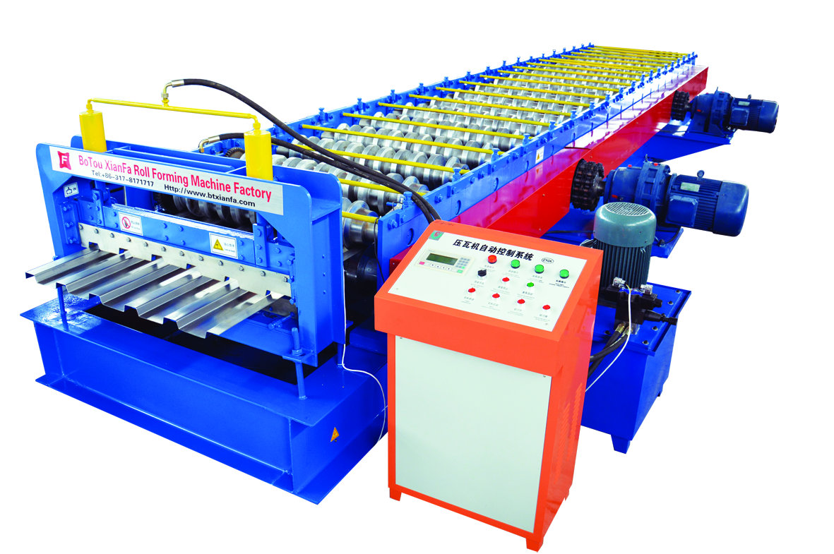
metal profile produced by Roll Forming Machine look beautiful, elegant and
noble. They are widely used for garden, factory, hotel, exhibition center and
villa, etc.
Cold Roll Forming Machine Components:
Roll forming machine consists of Uncoiler,
Coil sheet guiding device, Main roll forming system, Post cutting device,
Hydraulic station, PLC control system and Support table.
Optional with Hydraulic Decoiler, Auto Stacker, Safe Cover, Pre-Cutting, Film Covering Device, and so on.
Cold Roll Forming Machine Working
Flow:
Decoiling→Feeding & Guiding→Flattening(If
needed)→Pre- Punching/Cutting(If needed)→Roll Forming→Post Step
pressing/Punching(If needed)→Post Cutting→Finished Products To Support Table
Parameter:
9.Motor:4+4kw
Cold Roll Forming Machine Cold Roll Forming Machine, Cold Forming Machine, Cold Rolling Machine Botou Xianfa Roll Forming Machine Factory , https://www.rollforming.nl
1.Suitable to process:Colored Steel plate, galvanized board
2.Width of the plate:1000/1200/1250mm
3.Roller stations:10-19rows
4.Rolling material: Forging Steel 45#
5.Rolling galvanization thickness:0.05 mm
6.Material of the cutting blade :Cr12
7.Hydraulic oil :40#
8.Dimensions: 9000mm*1700mm*1600mm
10.Thickness of the plate:0.3-0.6mm
11.Productivity:8-10m/min
12.Diameter of the roller:70mm
13.Weight:About 4.6 T
14.Voltage:380V 50Hz
15.Processing precision : within 1.00mm
16.Transportation:one complete machine need one 40feet container
to hold
17.Payment term:30%deposit,and balance before delivery
18.Standard components: Chain 1 pcs, Hydraulic oil pipes: 2 pcs,
electromagnetism valves 1 pcs. limit switch:2 pcs
19.This machine is composed of feeding table,forming machine, pressing
device,cutting device, hydraulic system,computer control system,discharge table.
Optional devices have
manual uncoiler,hydraulic uncoiler,auto stacker and so on.