Eddy current sensor principle and performance parameter index
Thermal Handheld inkjet printer adopt HP TIJ2.5 technology, printing height is can be 1.5mm to 25.4mm,it can be use as handheld inkejt printer, and continuous inkjet printer if add extra lead rail and sensor, printing resolution up to 600dpi
HAE Inkjet Coding Machine adopt sealed ink cartridge, avoid ink ink pollution,and complex experiment and adjustment, it is maintenance-free, multifunctional.
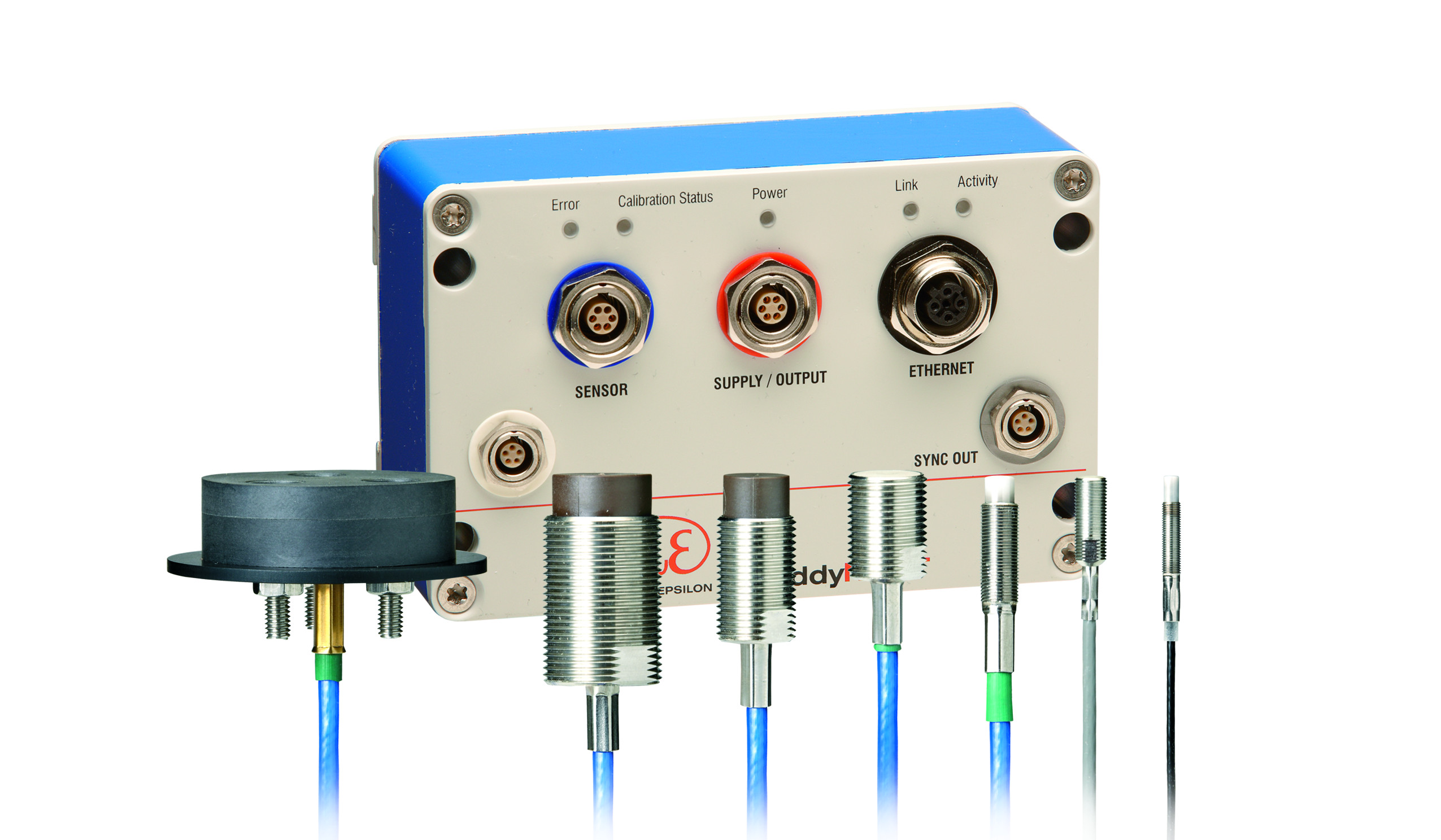
For position/displacement measurement and nanopositioning. According to Faraday's law of induction, eddy currents will be induced in metal conductors if the conductor is located in a time-varying magnetic field. The magnetic field here produces a wire coil that is current flowing in aternating. The magnetic field generated by this eddy current is the opposite and it overlaps with exciting magnetic fields. As a result, the changing impedance of the sensor coil Z.
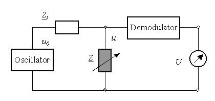
The impedance change depends on the distance between a measurement target (metal plate) and the sensor, while the target material. The change of impedance of a coil for a defined measurement target is a function of distance. Therefore, the distance can be obtained by measuring the impedance change. Using an impedance transformer (Figure 2), the impedance change can be converted into a voltage change for further signal processing.
Figure 1 Eddy Current Displacement Sensors Figure 2 Impedance Voltage Converters Eddy current sensors work most efficently at high oscillation frequencies near their resonant frequency. The resonant frequency of the eddy current sensor depends on the sensor coil. The serial impedance Zs must be high enough to obtain high sensitivity. The output voltage U of the output voltage after demodulation U disk as a function of the distance. Figure 3 shows the output signals at different frequencies. 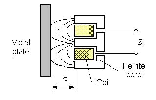
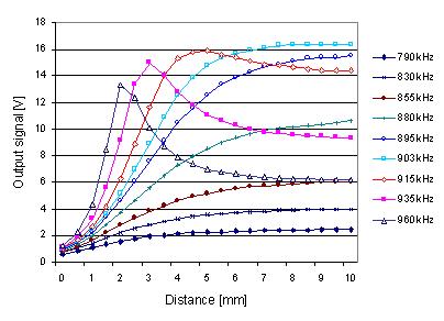
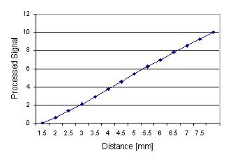
In order to increase the measurement range of the eddy current sensor, the linearity of the output signal must be improved by signal processing. The output signal at a frequency higher than the resonant frequency approximates an exponential function. In this case, one can use analog signal processing to produce a linear output voltage. Figure 4 shows each embodiment where the linearization of the output signal is at a frequency of 810 kHz. The linear range of the processed signal is greater than the amplification of the original signal. A linearity of less than 0.1% is achieved after sensor optimization.
Special sensor electronics, signal processing and self-calibration were developed for the compensation of temperature and material effects. Therefore, a distance eddy current sensor has been developed that is independent of the measurement object, and can accurately measure the position, distance and vibration measurement under normal conditions. 
Continuous Inkjet Printer,Rotary Inkjet Printer,Date Inkjet Printer,Chinese Inkjet Printer,Thermal Inkjet Printer,Handheld Inkjet Printer
Wuhan HAE Technology Co., Ltd. , https://www.chinahae.com