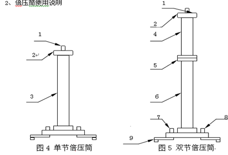
DC high voltage generator safety performance indicator
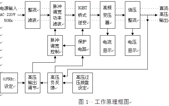
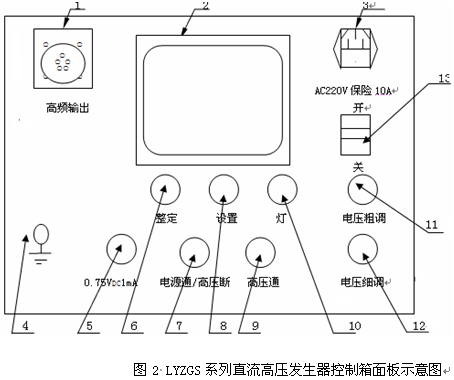
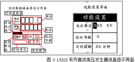
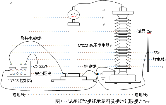
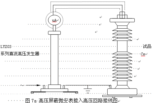
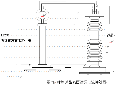
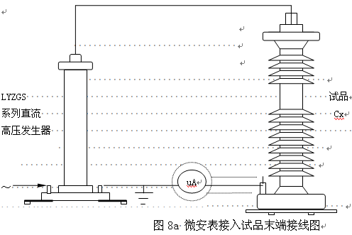
DC high voltage generator safety performance indicator I. Product Introduction According to the requirements of the Chinese industry standard ZBF 24003-90 "General Specifications for Portable DC High-Voltage Generator", the latest research, design and manufacture is a new era of scientific and technological products - portable DC high voltage generator, suitable for the power sector, Factory and mining enterprise power departments, scientific research units, railways, chemical industry, power plants, etc. conduct high-voltage DC high-voltage tests on zinc oxide surge arresters, magnetic discharge arresters, power cables, generators, transformers, and switches, which are the ideal new generation products in the new century. Using high-frequency voltage doubler circuit, the first to apply the latest PWM high-frequency pulse width modulation technology, closed-loop adjustment, the use of a large voltage feedback, so that the voltage stability greatly improved. The use of high-performance IGBT devices and their drive technology, and according to electromagnetic compatibility theory, using special shielding, isolation and grounding measures. Enables DC high voltage generators to achieve high quality, portable, and withstand rated voltage discharge without damage. The main components of the instrument are selected from advanced technology components from the United States, Germany, Japan, etc. to make the instrument more reliable and stable. The pressure tube is developed and manufactured using German technology. The high-frequency transformer is specially designed by the relevant experts, with small size and large capacity. Strong overload ability, convenient for on-site operation test. Looking ahead, companies will continue to actively explore the market. With quality and reputation as its lifeline, we have continuously improved the level of science and technology and developed cutting-edge high-quality products to meet the needs of users and strive to open up and recreate the glory of the new century. DC high voltage generator safety performance indicator Second, product characteristics 1. It is the most ideal and reliable product in the new century because it is smaller, lighter, more beautiful, more reliable, simpler in operation, full-featured and easy to use in the field. 2. Adopt advanced technology and process manufacturing, take the lead in applying the latest PWM high-frequency pulse width modulation technology, pulse string logic array modulation, and adopting high-power IGBT devices, using high-frequency technology to increase the frequency, the frequency up to 100kHz, so that the output high voltage stability Higher, the ripple factor is smaller. 3, according to maintenance-free design, the main components are selected from the United States, Germany, Japan and other countries imported advanced technology components, durable, not afraid of direct short-circuit discharge to the ground. 4, high precision and accurate measurement. Both voltage and current meters are digital display. The voltage resolution is 0.1kV and the current resolution is 0.1uA. The voltage meter on the control box directly displays the voltage value added to the load test sample. No voltage divider is needed when using, and the wiring is simple. The instrument has high and low voltage side to measure leakage current, and the high voltage end adopts round shield digital meter display. It is not afraid of discharge shock and has good anti-interference performance. It is suitable for field use. 5. High voltage regulation stability, full-range smooth voltage regulation, output voltage regulation adopts imported single multi-turn potentiometer, stable step-up process, high adjustment accuracy, and a coarse and fine adjustment function. The voltage regulation accuracy is better than 0.1%, the voltage and current measurement error is less than 1.0%, and the ripple factor is better than 0.5%. 6, negative output, zero start, continuously adjustable, there is over-voltage, over-current, return to zero, ground protection, unique disconnection protection and other protection functions. The automatic protection circuit has strong functions, perfect and reliable protection, and makes operation safe. All kinds of technical indicators are better than the industry standard and better than similar products. 7. Added the function of high precision 75% VDC-1mA to make the measurement of zinc oxide surge arresters very convenient. A simple press does not require calculation. The instrument control box has 75% voltage function keys. When doing the arrester test, when the current rises to 1000uA, it will open the 0.75 button. At this time, the value displayed by the voltmeter and ammeter is 75% of the data. Immediately after the boost knob is returned to the zero position, the fine voltage regulator will be returned to the zero position. Immediately press the green button to cut off the high voltage and turn off the power switch. Do other tests. 8, convenient over-voltage setting setting function, using a computer digital setting, as long as the setting keys and setting keys at the same time press, you can visualize the setting voltage value, so that you operate more freely, the display unit of value is kV. This machine has a time display setting function. Generator power start function 9, double pressure tube can be divided into sections structure, on-site use, flexible and convenient, more than one machine, economic benefits. 10. There are three built-in support feet at the bottom, which increases the stability of the pressure tube. DC high voltage generator safety performance indicator Third, electrical operation block diagram DC high voltage generator safety performance indicator Fourth, product specifications and main technical performance Specifications Technical Parameters 60/2 100/2 120/2 160/2 180/2 200/2 250/2 100/200 3/2 200/300 5/2 other grade Output voltage (kV) 60 100 120 160 180 200 250 100/200 200/300   600 ~ 800kV and other contracts Custom made. Output current (mA) 2 2 2 2 2 2 2 3/2 5/2 Output power (W) 120 200 240 320 360 400 500 400 600 Charging current (mA) 3.0 3.0 3.0 3.0 3.0 3.0 3.0 4.5/3.0 7.5/3.0 Chassis weight (kg) 4.3 4.3 4.3 4.3 4.3 4.4 4.5 4.5 8.1 Double cylinder height (mm) Φ80 ×500 Φ80 ×620 Φ80 ×770 Φ80 ×770 Φ110 ×770 Φ110 ×770 Φ110 ×820 Φ110 ×800 Φ110 ×1350 Double pressure weight (kg) 6.3 6.8 6.8 7.2 7.2 7.2 7.6 7.5 12.6 High voltage polarity Negative voltage polarity, zero voltage start, continuously adjustable. Working power AC 220V±10%; 50Hz Voltage measurement error 1.0% (full scale) ± 1 word, highest resolution 0.1% kV Current measurement error 1.0% (full) ± 1 word, highest resolution 0.1% uA Over-voltage setting error ≤1.0% 0.75 switching error ≤0.5% Ripple factor ≤1.0% Voltage stability Random fluctuation, ≤0.5% when the power supply voltage changes ±10% Way of working Discontinuous use; rated load 30 minutes; 1.1 times rated voltage use: 10 minutes Ambient temperature -15°C~50°C Relative humidity When the temperature is 25°C, no more than 90% (no condensation) Altitude 2500 meters or less DC high voltage generator safety performance indicator V. Instructions (1) High-frequency output and voltage and current measurement cables are quickly connected to multi-core sockets: They are used for the connection of the chassis and the voltage doubler part. When connecting, simply align the white point on the cable plug with the white point on the socket clockwise into place. When removing, just turn the cable plug counterclockwise. Note: When installing or removing the plug, hold the metal ring of the plug and rotate it. It is forbidden to hold the cable to rotate and pull the cable to rotate so as to avoid disconnection between the plug and the cable. (2) LCD display: display measurement data; voltage setting value; timing reminder; number of times of pressure, etc. The display content is related to your operation. (3) Power input socket: Single-phase AC 220V±10%, 50Hz. Connect the randomly-supplied power cord to the power input socket (with a fuse 10A or a separate fuse block in the socket). (4) Ground terminal: This grounding terminal is connected to the grounding terminal of the doubler cylinder and the grounding of the test object as a point and then connected to the grounding net. (5) 75% VDC-1mA yellow illuminated button: valid when the red light is on. When the yellow button is pressed after the yellow button is pressed, the output high voltage is reduced to 0.75 times the original, and this state is maintained. This function is specifically for the rapid measurement of zinc oxide surge arresters with 0.75VDC-1mA, press the green button red light, yellow light is off The high pressure cuts off and exits the 0.75-fold state. (6) (8) Function buttons: 1. Setting button: (Multi-function button) When you are using the generator power supply for testing, the machine will not start because it is not grounded, and an ungrounded prompt and flashing picture will appear on the screen prompt area; when you press After this button, the ungrounded alarm can be released after 3 seconds. The prompt area is still ungrounded, the picture stops flashing, and the machine can boost normally. 2. Setup button (multi-function button) When you need timed reminder, press this button in the real-time data interface to start the timer reminder. The timing indicator appears at the bottom left of the screen. The progress bar at the bottom of the data area starts to move. When the timer is full, the progress bar is full. Buzzer sounds. Pressing this button at any time will restart the timer. Multiplexing function: In the course of use, if you need to change the voltage setting value, remind the value of the timer, double the number of pressure, you can press the setting button, and then press the setting button to enter the function setting interface. (After entering the function setting interface, if there is no operation within 3 seconds, it will automatically return to the real-time data interface. In the function setting interface, please do not step up the voltage so as not to damage the machine and the sample). In the function setting interface Press the setting button, change the adjustment object {selected object is highlighted dim display} Press the Settings button to change the value of the object being adjusted (if the object is doubled, you can change the single and double (8) Single and double section selector switch (for double barrel), voltage full scale shift (section) switch: when the switch is dialed to 1, the double pressure tube is a single section, and the voltmeter shows a single section multiple pressure The barrel voltage; when the switch is turned to 2, the double pressure tube is double, and the voltmeter shows the double barrel pressure. When using the double-double pressure cylinder, align the lower flange white point mark of the upper section with the white point on the upper flange of the lower section and rotate clockwise until it touches the foot (about 30 degrees). The upper and lower sections are electrically connected in place. On the contrary, it was removed. When using in a single section, please do not forget to put the other end cap on the top and use the method described above to put it on the top of the next section. (7) Green illuminated button: The green light indicates that the power is on and the high voltage is disconnected. When the red light is on, press the green button, the red light is off and the green light is on, and the high pressure circuit is cut off. (9) Red illuminated button, high voltage connected button, high voltage indicator: When the green light is on, the red light will turn green and the high voltage circuit will turn on when the red button is pressed. It can be boosted at this time. This button is only valid when the voltage regulator potentiometer returns to zero. If the red button is pressed, the red light is on, the green light is still on, but the release button is red and green, indicating that the internal protection circuit is working. At this time, it must be turned off to check whether the over pressure setting dial switch is less than 5% of full scale and Whether there is any other fault, check it and restart it. (10) Light button: LCD backlight, if you test in a dim environment, press this button when the content on the screen is not clear, the backlight is on, and if you press it again, the backlight will be off. (11) Coarse adjustment voltage adjustment potentiometer: The potentiometer coarsely adjusts the multiturn potentiometer, clockwise rotation is the boost, otherwise it is the voltage drop. This potentiometer has a control electronic zero-position protection function. Therefore, you must return to zero before boosting. The voltage regulation accuracy is 0.1%kV. After the test is completed, the potentiometer should return to zero. (12) Fine-tuning the voltage regulator potentiometer: To adjust the accuracy, the potentiometer fine-tune the multi-turn potentiometer, clockwise rotation to boost, the boost pressure is very slow, and vice versa to reduce pressure. Fine tuning is generally used to adjust the voltage accuracy number and do the zinc oxide arrester test, and finally adjust the current accuracy number. After the test is completed, the potentiometer should return to zero. (13) Power switch: press this switch upwards, the power is turned on, and the green light is on; otherwise it is off. Avoid using this switch to directly turn off the high voltage. When shutting down, first make the voltage coarse adjustment and trimmer potentiometer return to zero, then turn off the power switch. 1.High voltage outlet terminal 2.Pressure cover 3. Double pressure cylinder 4. Upper double pressure cylinder 5. Upper and lower joint flanges 6. Lower section pressure tube 7. Ground terminal 8. Connection cable socket with control box 9. △-Y telescopic pin DC high voltage generator safety performance indicator Sixth, operation steps 1, ready to use (1) The integrity of the DC generator should be checked before use. There should be no open circuit and short circuit in the connection cable and no damage to the equipment. (2) Put the chassis and double pressure cylinder in a suitable and safe place, and connect the power cable, cable and grounding cable respectively. The protective grounding wire and the working grounding wire as well as the grounding wire of the discharge wand shall be separately connected to the ground of the sample (ie, one point grounded). It is forbidden to use each grounding wire in series with each other, so as to avoid the formation of counterattack when the breakdown voltage rises and damages the instrument. (See Figure 6) (3) Check if the power switch is in the off position, and check that the voltage regulator is in the zero position. The overvoltage protection setting dial switch is set at an appropriate position, typically 1.10 to 1.20 times the test voltage value. 2, no-load boost verification over-voltage protection settings (1) Please look for the power supply is single-phase AC 220V, 50Hz. Turn on the power switch, then the green light, indicating that the power is on. (2) Press the red button, the red light is on, which means the high voltage is on. (3) The adjustment of the coarse and fine adjustment of the piezoelectric positioner is smoothly and clockwise, and the output terminal is boosted from zero. After rising to the required voltage, record the ammeter reading according to the specified time, and check the control box and the output cable for abnormal phenomena and sound. If necessary, calibrate the DC high voltage indication on the control box with an external high voltage divider. (4) After the pressure is reduced, the pressure regulator will be returned to zero, and then press the green button to cut off the high voltage and turn off the power switch. 3, Leakage and DC voltage withstand test on the test sample (1) Before doing the load test, install the high-voltage shielded microampere meter on the high-voltage output end of the high-pressure doubler cylinder, and connect the special shielded cable to the microampere meter and the tested product respectively (see high voltage for details Shielding Microammeter Operation Manual). (2) Check whether the instrument, discharge rod, double pressure cylinder, test product connection line and grounding line are correct, and whether the grounding line connection is reliable. Check whether the high pressure safety distance meets the requirements before starting the high pressure test of the sample. (3) After confirming that there is no abnormality in the instrument, etc., turn on the single-phase AC 220V power switch. At this time, the green light is on, indicating that the power is on. The DC leakage and DC voltage withstand test of the test sample can be started. (4) When the red button is pressed, the red light is on, indicating that the high pressure is on and the pressure is to be raised. (5) The adjustment of the coarse and fine adjustment of the piezoelectric positioner is smoothly and clockwise, and the output terminal is boosted from zero. The step-up rate is preferably 3-5 kV per second to increase the test voltage. For a bulk capacitor, the sample must be slowly boosted during boost, otherwise it may result in voltage overshoot. It is also necessary to monitor that the charging current of the ammeter does not exceed the maximum charging current of the dc generator. When the desired voltage or current is reached, the ammeter and voltmeter readings are recorded for the specified time. (6) After the test is completed, step down and adjust the coarse and fine adjustment of the piezoelectric device to zero. Then press the green button to cut off the high voltage and turn off the power switch. (7) After the test is completed, use the discharge rod to discharge the sample for multiple discharges, and then discharge the sample and remove the wire. (Please refer to the discharge stick manual for details.) For small capacitor samples such as zinc oxide surge arresters, magnetic discharge arresters, etc., first increase to 90% of the required voltage (current) with a coarse adjustment, and then gradually increase the voltage to the desired voltage (current) value with a fine adjustment potentiometer. Then read the voltage (current) value from the digital meter. If you want to measure the 75% VDC-1mA of the zinc oxide surge arrester, you should first rise to 1mA when the current value stops (in this case, record the voltage and current value), then press the yellow button, the voltage will drop to the original value. 75% and keep this state. At this point, the microampere meter values ​​and voltage values ​​can be read. After the measurement is completed, adjust the piezo-electric counter to return to zero counterclockwise, press the green button, and press the red button when you need to raise the pressure again. For large capacitance test samples, the boost should be even slower, and it is necessary to monitor that the charging current of the ammeter does not exceed the maximum charging current of the generator, and the boosting speed must be slowed to avoid excessive charging current. After the test is completed, turn the voltage adjustment potentiometer counterclockwise back to zero, then press the green button to cut off the high voltage. At this point, note that the voltage on the voltmeter drops to about 15kV, and the discharge rod can be used for multiple discharges to ensure safety. 4, several measurement methods (1) In general measurement, when the wire is connected, the line connecting the test sample is vacant, and after rising to the test voltage, the corona and stray current I′ at the time of the air test are read, and then the test sample is brought up to the test voltage. The total current I1 is read. Sample leakage current: I0=I1-I′ (2) When it is necessary to accurately measure the leakage current of the test object, a high voltage shielding microammeter should be connected in series in the high voltage circuit, as shown in Figure 7a. Figure 7a High-voltage shielding microampere meter access sample Cx high-voltage side wiring diagram. The high-voltage shielding microampere meter must have metal shielding, and the shielding wire should be connected with the test sample. The shielding lead of the high voltage wire should be closely connected with the shielding of the instrument end. If you want to rule out the influence of the surface leakage current of the sample, you can connect it with the shielding of the high-voltage lead after tightly winding the bare metal flexible wire at the high potential end of the sample (see Figure 7b). (3) When the grounding terminals of the zinc oxide surge arrester, magnetic discharge arrester, etc., are separable, it is also possible to use a current meter in series at the bottom (ground potential side) of the test sample for measurement, but shielded wires must also be used (see the figure 8a). When the influence of the surface leakage current of the test piece is to be excluded, a bare bare copper wire can be connected to the shield at the ground potential end of the test piece for a few turns (see Figure 8b). (4) After the test is completed, step down and adjust the positioner back to zero. Then press the green button to cut off the high voltage and turn off the power switch. (5) For small-capacity samples such as zinc oxide surge arresters, the discharge is usually performed through a piezoresistor and the time is very short. For large-capacitance test items such as cables and motors, it is generally necessary to wait until the voltage of the test sample self-discharges to less than 20% of the test voltage, and then discharge through the discharge bars. After the sample to be fully discharged and the grounding wire is hung, the removal of the high voltage lead wire and the replacement of the wiring work are allowed. 5, operation after protection action In the course of use, it is found that the red light is off, the green light is on, and the DC high voltage is down, which is the related protection action. At this point, follow these steps: (1) Return the positioner to zero. (2) Turn off the power switch and the panel indicators are off. (3) After one minute, the low-voltage capacitor in the standby is fully discharged and the power switch is allowed to turn on again. After re-doing the no-load test and ascertaining the situation, the test may be boosted again. DC high voltage generator safety performance indicator Seventh, fault inspection and processing No. Failure the reason Approach 1 When the power switch is turned on, the green light is off and the fan does not turn on (some control boxes have no fan). 1. The power cord is open. 2. The power fuse blows. Replace the power cord, Replace the fuse. 2 Press red button does not light red. The regulator does not return to zero. The potentiometer returns to zero. 3 Press the red button red light, the green light is not off, the hand release red light off. Protection action over-voltage protection setting less than 5-10% (full scale). Set the digital dial switch to the proper value. 4 Press red button red light, one boost red light off, green light. Place the ground on the high voltage output and short-circuit the sample. Check the output cable and check the sample. 5 During the boosting process, the red light is off and the green light is on. The test sample discharge or blow through the pressure or overcurrent protection action. Check the test item and reset the setting value. DC high voltage generator safety performance indicator Eight, current limiting resistor instructions 1. Current limiting resistor function: When the test piece breaks down or flickers, it acts as a limiting current, so as not to damage the test equipment. 2. How to use: As long as the M10 nut at one end of the current limiting resistor is screwed to the top of the double pressure cylinder of the DC high voltage generator, the high voltage output line bolt can be on. If you want to connect the high-voltage microammeter series (optional SWB-V type table), just screw the M10 nut at the bottom of the microammeter to the other end of the current limiting resistor. 3. If LYZGS series DC high-voltage generators are used, the test samples are zinc oxide surge arresters, pre-valve arresters, and high-voltage switches and other electrical equipment, which do not require current limiting resistors. In other words, current-limiting resistors are not required for small-current, small-capacitance samples. 4. For large-capacity test items such as power cables, transformers, and motors, the current limiting resistor should be connected in series in the high-voltage loop to protect the test equipment. DC high voltage generator safety performance indicator Nine, matters needing attention 1. Be sure to check the connection line and grounding cable correctly, and the grounding of each part is good. Do not connect the grounding line in series. Pay attention to the safety distance and ensure personal safety. 2. After each test, the leveler should be returned to zero position (rough adjustment and fine adjustment are all back to zero). Press the green button to cut off the high voltage and turn off the power switch, and finally discharge. 3. Do not turn on the instrument without permission. This will affect the product warranty. It is not responsible for the dismantling of the factory. 4. When the instrument is transported, rain erosion should be avoided to prevent collisions and crashes. DC high voltage generator safety performance indicator Ten, product set 1, control the chassis 1; 2, high pressure double pressure tube 1 (or 2); 3, power cord 1; 4, high frequency output multi-core cable 1; 5, spare fuse 10A only a few; 6, the use of manual 1; 7, product inspection certificate, warranty card 1; 8, product acceptance test report 1; 9, 1 discharge rod; 10, a dedicated ground wire 1; 11. Discharge rod instruction manual 1 copy. DC high voltage generator safety performance indicator Eleven, optional 1, SWB-V high voltage shielding microampere meter; 2, various specifications of high-voltage output cables and special lead clips; 3, a variety of specifications are pressure enclosures (for the Bureau to put the test); 4, current limiting resistance; 5, various specifications of aluminum alloy box. 1. Naipu HH serieshorizontal Slurry Pump are designed to produce high head per stage at high pressures.
commonly used for long distance transport lines, the NP-HH lines can
often satisfy application duties with a single pump where others require
multiple pumps.the range is capable of handling medium size particles
and pumping at heads in excess of 90 meters per stage.
Bottom Boiler and Fly Ash
Mill Discharge
2.Construction drawing of HH series Horizontal Slurry Pump
3.Select chart of HH series horizontal slurry pumps
4.HH series slurry pump performance parameters
HH High Head Horizontal Slurry Pump HH High Head Slurry Pump,HH Slurry Pump,High Head Pump,HH Pump Shijiazhuang Naipu Pump Co., Ltd. , https://www.naipu-pump.com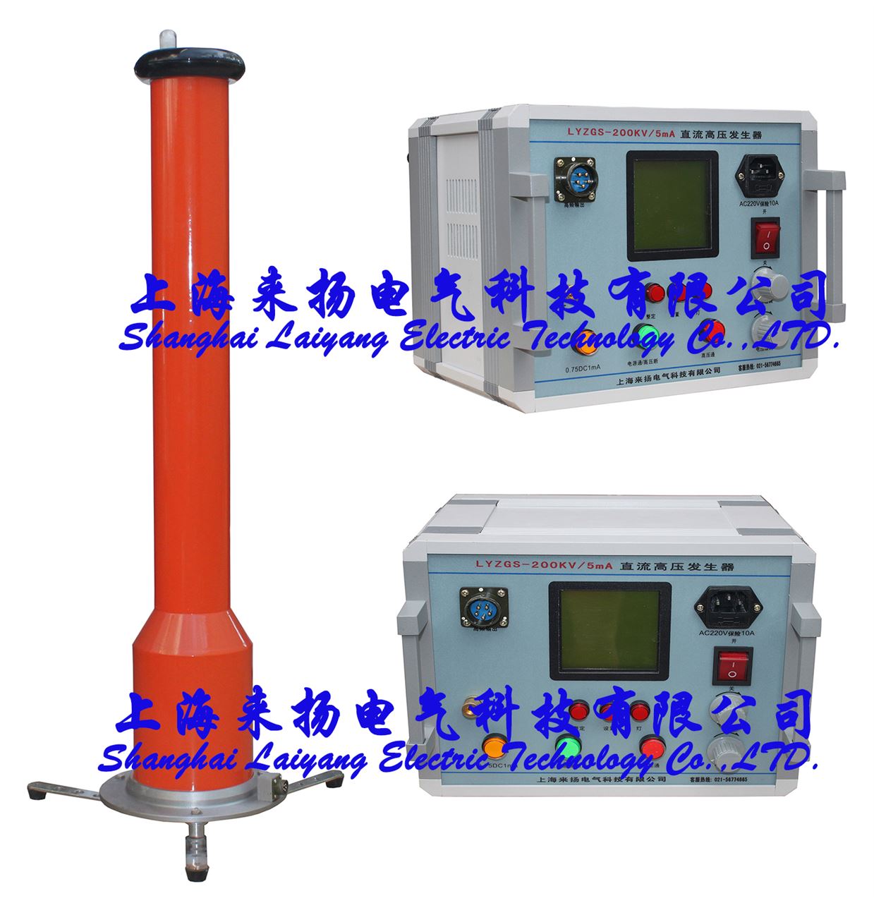

Typical Applications---
Tailings Delivery
Cyclone Feed
Diamond Concentrate
Slag Granulation


