Fan Basics: Air Flow, Static Pressure, and Impedance
June 21 03:22:31, 2025
Sure! Here's the rewritten content in English:
---
Do you know how to interpret this graph?
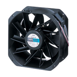
Below is a visual representation provided by manufacturers to showcase the performance of their fans. This is where the specifications for air flow and static pressure come from.
For many customers, this might seem confusing. Often, people choose fans based on size and air flow alone. However, understanding these details is crucial for determining how a fan will perform in real-world situations.
In this article, I’ll explain the difference between air flow and static pressure, their relationship, and the significance of impedance.
**Airflow vs Static Pressure**
In the fan specifications table above, you’ll notice “Maximum Air Flow†and “Maximum Static Pressure.â€
Air flow refers to the volume of air a fan can move over time. It’s typically measured in cubic meters per minute (m³/min) or cubic feet per minute (CFM). To simplify, if you have a 5 ft x 5 ft x 5 ft enclosure and a fan producing 5 CFM, it would likely take around 25 minutes for the fan to ventilate the hot air inside. (Of course, it’s not always that straightforward.)
Static pressure, on the other hand, is the air pressure a fan can generate within an enclosure. It’s measured in Pascals (Pa) or inches of water (inH₂O). A Pascal (Pa) is the SI unit for pressure, defined as one Newton per square meter. One inch of water (inH₂O) at 4°C is roughly equal to 249.082 Pascals.
It’s important to note that even though maximum values for air flow and static pressure are listed, the fan won’t output both maximum values simultaneously.
The relationship between air flow and static pressure is illustrated in the graph above. As you can see, air flow and static pressure are inversely related. Higher air flow results in lower static pressure, and vice versa. The three points depicted represent possible fan performance scenarios.
To better understand these scenarios, imagine ventilating an electronics enclosure with a fan. Refer to the graph above with the three points labeled 1), 2), and 3).
In example 1), the enclosure is completely open on one side. With no obstructions, all the air flows out easily, leading to maximum air flow and zero static pressure.
In example 2), the enclosure is mostly sealed, except for a small exhaust hole on the other end. The smaller exhaust hole restricts air flow, causing static pressure to build up. This reduces the air flow below its maximum capacity.
In example 3), the enclosure is entirely sealed. The trapped air increases static pressure, eventually reaching the fan’s maximum static pressure limit. Beyond this point, even if the fan keeps running, no additional air can enter. Thus, air flow drops to zero.
In practical applications, examples 1 and 3 aren't typical. For ventilating an electronics enclosure, most fans would behave closer to example 2. However, to create the graph, a similar method called the double chamber method is used.
**Installation Density**
Now that we’ve covered air flow and static pressure using an electronics enclosure as an example, let’s make it more realistic. Enclosures house essential electrical components like PLCs, power supplies, and motion control drivers. Since these enclosures often contain heat-generating elements, fans are vital for maintaining optimal temperatures.
The number of components inside an enclosure affects what we call “installation density.â€
With fewer components (low installation density), there’s more space for air to circulate, resembling example 1, where the fan achieves higher air flow.
With more components (high installation density), the air flow faces more obstacles, similar to example 2. In such cases, high static pressure can reduce the air flow below its maximum value.
**The Importance of Impedance**
So, how do we determine the actual air flow and static pressure requirements? The answer lies in impedance. Impedance refers to the resistance air encounters as it moves through the system, whether due to electronic components, walls, or other barriers. The actual air flow and static pressure are determined by impedance.
Here’s how it works. For most forced-air cooling applications, impedance is calculated using the "square law," meaning static pressure varies as a square function of changes in CFM.
\[ P = K \cdot r \cdot Q^n \]
Where:
- \( P \) = static pressure
- \( K \) = load factor (some reference information here)
- \( r \) = fluid density
- \( Q \) = flow rate
- \( n \) = constant; let \( n = 2 \), approximating a turbulent system.
In the graph below, three yellow lines represent three different levels of impedance (A, B, and C).
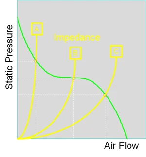
The green line shows both air flow and static pressure. Point A represents high impedance, while point C represents low impedance. The actual air flow and static pressure are determined at the intersection of the impedance curve (yellow) and the performance curve (green).
Sometimes, calculating system impedance can be challenging. In such cases, it’s safer to assume that the actual air flow will be about half of the fan’s maximum air flow, so you should select a fan that can produce twice the required air flow.
For a successful enclosure ventilation design, beyond fan selection, other factors such as intake/exhaust hole size, hole placement, and component arrangement must be considered. In the following video, we use smoke to demonstrate how different enclosure designs, like varying intake hole diameters and the use of dividers, affect air flow.
[Embed video link]
Accessories like filters, screens, or finger guards can enhance fan reliability and lifespan in dusty or humid environments, but they also impact air flow and static pressure characteristics.
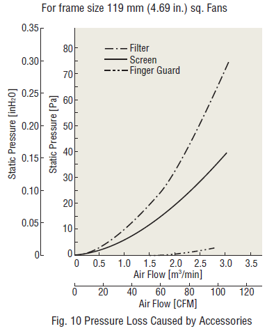
The graphs above show pressure loss data caused by fan accessories for a 4.69-inch frame size fan. Filters cause the most significant pressure loss, whereas finger guards have minimal impact.
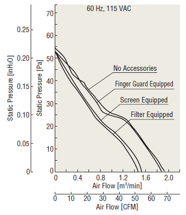
This graph demonstrates how characteristics may change when accessories are installed, using the MU1225S-21 fan as an example. Greater pressure loss leads to a more substantial reduction in air flow and static pressure characteristics.
If you’d like to learn more about fans, check out our resources below. Topics include:
- Cooling Fan Structure, Air Flow Static Pressure Characteristics, and Heat Protection
- How to Select a Cooling Fan
- IP Ratings - Degree of Protection
---
I hope this helps! Let me know if you need further adjustments.