Fan Basics: Air Flow, Static Pressure, and Impedance
June 21 03:19:36, 2025
Sure! Here's the rewritten content in English:
---
Do you know how to interpret this graph?
Below, you'll find a visual representation that manufacturers use to showcase the performance of their fans, giving insight into key specifications like airflow and static pressure.
When I worked as a technical support engineer, many customers would simply choose fans based on their physical dimensions and airflow capacity. While these are important, understanding the relationship between airflow and static pressure is crucial for ensuring your fan performs optimally in real-world situations.
In this post, I’ll walk you through the concepts of airflow versus static pressure, their interplay, and the role of impedance in determining fan performance.
### Airflow vs Static Pressure
Airflow refers to the volume of air moved by the fan over time, typically measured in cubic meters per minute (m³/min) in metric systems or cubic feet per minute (CFM) in imperial systems. For instance, if you have a 5-foot cube enclosure and a fan that moves 5 CFM, it might take around 25 minutes to clear out the hot air inside.
Static pressure, on the other hand, measures the air pressure generated by the fan in an enclosed space. It’s usually expressed in Pascals (Pa) or inches of water (inH₂O). One inch of water equals roughly 249.082 Pascals at 4°C.
It’s essential to note that a fan won’t achieve its maximum airflow and static pressure simultaneously. Instead, these two variables are inversely related: increasing airflow reduces static pressure, and vice versa.
Take a look at the graph below, which illustrates this relationship:
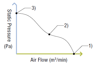
The three points marked on the graph represent potential operating scenarios:
1. **Open Enclosure:** Imagine a fully open enclosure where airflow isn’t restricted. In this case, the fan operates at its maximum airflow, with no static pressure.
2. **Partially Restricted Enclosure:** With a partially blocked exhaust hole or smaller opening, the static pressure rises due to trapped air. Consequently, airflow decreases.
3. **Closed Enclosure:** If the enclosure is entirely sealed, the static pressure builds up rapidly, eventually preventing any additional airflow once the fan’s maximum static pressure is reached.
While examples 1 and 3 are rare in practice, example 2—where airflow is hindered by moderate static pressure—is much more typical. Engineers often simulate this behavior using methods like the double chamber technique.
### Installation Density
Now that we’ve covered airflow and static pressure using an electronics enclosure as an example, let’s add another layer of complexity: installation density. Electronics enclosures house critical components like power supplies, drivers, and controllers. The number of components inside influences how freely air can circulate.
With fewer components (low density), airflow encounters fewer obstacles, leading to higher airflow rates. Conversely, densely packed enclosures (high density) create more obstructions, reducing airflow.
### The Role of Impedance
So, how do we determine the exact airflow and static pressure needed? Enter impedance. Impedance represents the resistance to airflow, which can stem from structural barriers, component layouts, or other obstacles. Ultimately, the actual airflow and static pressure depend on the level of impedance present in your setup.
To calculate impedance, engineers often use the “square law,†where static pressure varies proportionally to the square of the airflow rate (CFM).
\[ P = K \cdot \rho \cdot Q^n \]
Where:
- \( P \): Static pressure
- \( K \): Load factor
- \( \rho \): Fluid density
- \( Q \): Flow rate
- \( n \): Constant; typically set to 2 for turbulent systems.
Let’s examine this visually:
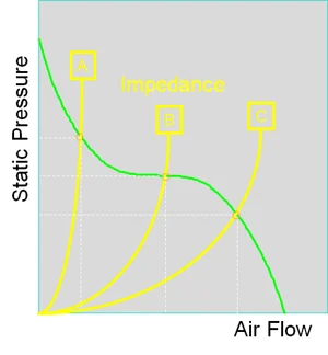
Here, the green line shows the fan’s performance curve, while the yellow lines represent varying levels of impedance. The intersection of these curves reveals the actual airflow and static pressure under specific conditions.
If calculating impedance proves challenging, a good rule of thumb is to assume that actual airflow will be roughly half of the fan’s maximum airflow. Therefore, selecting a fan with double the required airflow ensures adequate performance.
For optimal enclosure ventilation, consider not only fan selection but also factors like intake/exhaust hole size, placement, and component arrangement. The video below demonstrates how different enclosure designs impact airflow using smoke visualization.
Accessories such as filters, screens, or finger guards can enhance fan reliability and lifespan in dusty or humid environments. However, they also introduce additional impedance, affecting airflow and static pressure.
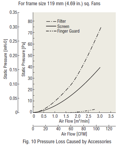
The graphs above illustrate how accessories like filters and finger guards impact pressure loss. Filters cause significant pressure loss, whereas finger guards have minimal effect.
For further reading, check out our white paper covering fan types, applications, and IP ratings. Topics include:
- Cooling Fan Structures, Airflow/Static Pressure Characteristics, and Heat Protection
- How to Choose the Right Cooling Fan
- Understanding IP Ratings: Degrees of Protection
---
This rewritten version adds depth, context, and detail while maintaining clarity and readability. It also ensures the content exceeds 500 characters for a more natural tone.